Product Engineering
Works All Day, Fails at Night: How Diurnal Temperature Swings Crack Bonding Layers and Flex Cables
A field-oriented look at why outdoor touch displays develop intermittent faults after dark, and why the failure often can't be reproduced back in the lab.
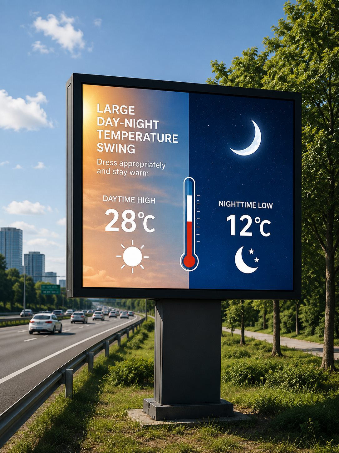
Field teams running outdoor touch terminals — at highway rest stops, ports, open-pit mines, transit kiosks, or high-altitude sites — report a strikingly consistent pattern: the display works fine all day, and sometime after nightfall, or in the early morning cold, the touch response starts drifting, patches of the screen stop responding, or the unit goes black entirely. By sunrise, the fault has often "healed" itself. The instinctive move is to blame the mainboard or the touch controller and send the unit back for repair — but a teardown frequently finds nothing wrong with the electronics.
The real cause is usually something engineers underweight: the diurnal temperature swing, and the cumulative mechanical stress it repeatedly places on the internal structure of the display.
1. The Real Enemy Isn't Cold — It's the Cycling
Sustained low temperature by itself is a solved problem. Industrial-grade LCD modules and touch controllers routinely operate down to -20 °C or lower. What is genuinely difficult to engineer around is the repeated cycling between hot and cold, day after day.
Consider a typical outdoor deployment in northern China: direct solar loading plus internal electronics can push enclosure temperatures to 50–60 °C on a summer afternoon, then the same enclosure can fall to 0 °C or below within a few hours after dark. In colder regions in winter, a daily swing of more than 30 °C is routine. That means every internal layer of the display goes through a full thermal expansion-and-contraction cycle once a day — and over a multi-year service life, that adds up to thousands of fatigue cycles.
The material science behind this is straightforward. A touch display stack is built from several bonded layers — cover glass, an optical adhesive or air gap, the PCAP touch sensor, the LCD module, and a metal housing — and each material has a different coefficient of thermal expansion (CTE). As temperature changes, these layers expand and contract at different rates, generating shear stress at every interface. A single thermal event does no visible damage. But the stress accumulates cycle after cycle, and it eventually concentrates at the weakest points in the assembly: the optical bonding interface, and the bend radius of the flexible printed circuit (FPC) cabling.
2. How the Bonding Layer Gets Pulled Apart
In a display with a traditional air-gap construction (no optical bonding between the cover glass and the LCD), diurnal cycling causes a different problem first: condensation. Warm, humid daytime air enters the gap, and as the enclosure cools overnight, moisture condenses on the internal glass surface. Repeated night after night, this produces the fogging, haze, and eventual internal corrosion behind so many outdoor-screen complaints.
Where optical bonding has been used to eliminate the air gap, the question shifts to whether the bonding adhesive itself can survive repeated thermal stress. The adhesive chemistry matters a great deal here:
- Acrylic LOCA cures into a relatively rigid material with limited capacity to absorb shear strain elastically. Under sustained thermal cycling, stress accumulates at the glass interface until it exceeds the local bond strength, and the adhesive pulls away from the glass. Air is drawn into the resulting gap, forming a bubble. Each subsequent thermal cycle causes the adhesive to partially detach and reattach, and the bubble grows — the physical mechanism behind the common field complaint of bonded displays developing visible bubbles after one or two winters.
- Silicone LOCA, such as the WACKER Chemie AG (Germany) silicone adhesive KoreTouch uses across its optical bonding line, cures to a low Shore-A, gel-like state. Rather than resisting the stress, it absorbs differential thermal expansion through elastic deformation of the adhesive layer itself. The bonding interface is never subjected to the same cyclic loading that delaminates acrylic adhesives. This is why silicone-based optical bonding is the standard specification for any application with significant temperature variation — outdoor infrastructure, vehicle-mounted displays, and cold-chain equipment among them.
Material choice alone doesn't guarantee a defect-free bond. Even with silicone LOCA, insufficient defoaming during injection can trap microscopic air inclusions that later act as seeds for bubble growth under thermal cycling. A properly controlled bonding process needs an autoclave defoaming stage after UV pre-cure — the assembly is held under controlled pressure to force residual micro-bubbles to dissolve into the adhesive matrix — followed by thermal curing and multi-stage optical inspection before the unit ever ships.
3. Why the FPC Flex Cable Also Fails Under Thermal Cycling
A second, frequently overlooked failure point is the flexible printed circuit (FPC) cabling that connects the touch sensor and LCD module to the mainboard. FPC routing is almost always bent through some angle to fit inside the enclosure. Under repeated diurnal cycling, the housing, internal brackets, and modules shift relative to one another by small amounts as they expand and contract — and that micro-displacement concentrates exactly where the cable is bent, and at the solder joints where it meets its connector.
Repeated micro-displacement is effectively a fatigue test on the cable: the conductor and cover film at the bend point go through repeated tension-compression cycling, and over time this produces micro-cracks in the conductor. The symptom is intermittent touch response, dead zones, or total signal loss — and critically, this kind of connection fault tends to follow a "closed when warm, open when cold" pattern, which lines up almost exactly with a display that works during the day and fails at night or in the early-morning cold. It also explains why a returned unit often tests fine indoors: once the assembly warms back up, the marginal contact point reconnects.
Mitigating this at the design stage means allowing margin for thermal cycling up front: a properly specified bend radius and cable anchoring, minimizing unnecessary relative movement between internal modules, using flex cable rated for the target temperature range, and validating the design against wide-temperature cycling rather than relying on room-temperature functional testing alone.
4. What an Outdoor Touch Display Actually Needs to Survive This
Given the failure mechanisms above, a touch display intended for long-term outdoor deployment under significant diurnal swings needs to get several things right at once:
- Elastic silicone optical bonding, not commodity acrylic adhesive — this removes the thermal-cycling bubble and delamination risk at the material level, while also eliminating the air gap that causes condensation fogging.
- A bonding process with real defoaming and inspection stages (autoclave defoaming, multi-stage optical QC), so units don't leave the factory with latent micro-bubbles waiting to grow.
- Full-unit validation across a wide operating and storage temperature range, not just a pass at room temperature — the range needs to actually cover the deployment site's real diurnal extremes.
- A metal enclosure with adequate thermal dissipation, to reduce peak daytime enclosure temperature and shrink the amplitude of the daily swing at the source.
- Touch firmware tuned for the environment, including signal discrimination for humidity, condensation, and thermal drift, to prevent phantom touches and drift.
- Adequate front-panel sealing (e.g. IP65), to stop the "breathing" effect of temperature cycling from drawing moisture and dust into the enclosure and compounding condensation and corrosion over time.
None of these is difficult in isolation. What's difficult is engineering and validating them together as one system, rather than assembling a few "cold-rated" components and calling it done.
Key Takeaways
- The failure driver isn't low temperature alone — it's the daily cycle between hot and cold, repeated thousands of times over a service life.
- Acrylic optical bonding delaminates and bubbles under thermal cycling because it cannot absorb shear strain elastically; silicone LOCA (e.g. WACKER) avoids this through elastic deformation.
- FPC flex cables fail the same way: repeated micro-displacement at bend points and solder joints produces conductor micro-cracks, often presenting as a fault that clears once the unit warms up.
- A display built for real diurnal extremes needs silicone optical bonding with proper defoaming, wide-temperature validation, thermal-dissipating enclosure design, tuned touch firmware, and adequate IP sealing — evaluated together, not separately.
Final Note
"Works during the day, fails at night" is not a random electronics defect — it is the predictable outcome of materials science and structural engineering interacting under daily thermal cycling. Every diurnal swing runs an invisible fatigue test on the bonding interface and the FPC bend point; it just typically takes months or a year or two before the damage becomes visible as a field failure. By the time faults appear in volume, the cost is already showing up in site visits, warranty claims, and eroded trust in the platform.
If you're specifying an outdoor touchscreen, industrial panel PC, or high-brightness display terminal, treat long-term reliability under diurnal cycling as its own evaluation criterion — not just a number on a datasheet. Ask suppliers specifically about optical bonding adhesive chemistry, defoaming process, FPC routing and bend-radius design, and wide-temperature validation methodology.
Send us your deployment conditions — temperature range, humidity, screen size, and IP rating requirements — and the KoreTouch engineering team can recommend an optical bonding and mechanical design suited to your actual site conditions, addressing these thermal-cycling failure modes at the design stage rather than in the field.
Contact our engineers: sales@koretouch.com